API 598 Pressure Test Specifications
API 598 covers pressure test requirement, test pressure, leakage class and test duration etc for resilient-seated, nonmetallic-seated , and metal-to-metal-seated valves including gate valve, globe valve, plug valve, ball valve, check valve, and butterfly valve.
Table 1—Pressure Test Requirement
| Test Description | Size | ASME Class | Valve Type | |||||
| Gate | Globe and Parallel Slide Gate | Plug | Check | Floating Ball | Butterfly and Trunnion Mounted Ball Valve | |||
| Shell | All | All | Required | Required | Required | Required | Required | Required |
| Backseat a | All | All | Required | Required | NA | NA | NA | NA |
| Low-pressure closure | DN (NPS) < DN 100 (NPS 4) | Class < 1500 | Required | Optional b | Required f | Optional b | Required | Required |
| Class > 1500 | Optional b | Optional b | Optional b | |||||
| DN (NPS) > DN 100 (NPS 4) | Class < 600 | Required | Required f | Required | ||||
| Class > 600 | Optional b | Optional b | Optional b | |||||
| High-pressure closure c | DN (NPS) < DN 100 (NPS 4) | Class < 1500 | Optional b e | Required d | Optional b e f | Required | Optional b e | Optional b e |
| Class > 1500 | Required | Required | Required | |||||
| DN (NPS) > DN 100 (NPS 4) | Class < 600 | Optional b e | Optional b e f | Optional b e | ||||
| Class > 600 | Required | Required | Required | |||||
| NA Not applicable | ||||||||
a The backseat test is required for all valves that have the backseat feature, except for bellows seal valves.
b When an “optional” test is specified by the purchaser, the test shall be performed in addition to the required tests.
c The high-pressure closure test of resilient-seated valves may degrade subsequent sealing performance in low-pressure service.
d For power-operated and manually operated gear actuated globe valves, including nonreturn type globe valves, the high-pressure closure test shall be performed at 110 % of the design differential pressure used for sizing of the operator.
e A high-pressure closure test is required for all valves specified to be double block and bleed (DBB) valves, unless specified otherwise by the purchaser.
f For lubricated plug valves, the high-pressure closure test is mandatory and the low-pressure closure test is optional.
Table 2—Shell Test Pressures d
(for Steel and nonferrous alloys body valves)
| Valve Type | Class | Shell Test Pressure (Minimum) | |
| Bar (Bar Gauge) | psig (Pounds per Square Inch Gauge) |
||
| Flanged | 150 to 2500 | b | b |
| Butt weld | 150 to 4500 | b | b |
| Threaded a and socket weld | 800 | c | c |
| 150 to 4500 | b | b | |
a ASME B16.34 limits threaded-end valves to Class 2500 and lower.
b Per ASME B16.34, the shell test pressure shall be 1-1/2 times the pressure rating at 38 ℃(100 °F), rounded off to the next higher bar (25 psig). The attachment of hubs, flanges, or other end connections with ambient working pressures lower than the primary valve assembly will require lower test pressures.
c For Class 800 valves, the shell test pressure shall be 1-1/2 times the pressure rating at 38 °C (100 °F), rounded off to the next higher bar (25 psig) (see API Standard 602[4]).
d Shell test pressure for API Standard 609 Category A valves shall be 1% times the maximum CWP of the valve.
Table 3—Backseat and Closure Test Pressures
| Test | Test Pressure d | |
| Bar (Bar Gauge) | psig (Pounds per Square Inch Gauge) | |
| Valves Except Butterfly and Check | ||
| High-pressure closure and backseat a | b | b |
| Low-pressure closure and backseat a | 5.5 ± 1.5 | 80 ± 20 |
| Butterfly Valve | ||
| High-pressure closure | c | c |
| Low-pressure closure | 5.5 ± 1.5 | 80 ± 20 |
| Check Valve | ||
| High-pressure closure | ||
| Class 125 (cast iron) | ||
| DN 50 to 300 (NPS 2 to 12) | 14 | 200 |
| DN 350 to 1200 (NPS 14 to 48) | 11 | 150 |
| Class 250 (cast iron) | ||
| DN 50 to 300 (NPS 2 to 12) | 35 | 500 |
| DN 350 to 600 (NPS 14 to 48) | 21 | 300 |
| Class 150 (ductile iron) | 17 | 250 |
| Class 300 (ductile iron) | 44 | 640 |
| Carbon, alloy, stainless steel, and special alloys | b | b |
| Low-pressure closure (see Table 1) | 5.5 ± 1.5 | 80 ± 20 |
a The backseat test is required for all valves that have the backseat feature, except for bellows seal valves.
b 110 % of maximum allowable pressure at 38 ℃(100 °F) in accordance with the applicable purchase specification.
c 110 % of design differential pressure at 38 °C (100 0F) in accordance with the applicable purchase specification.
d Single values shown are minimum test pressures. Values with a tolerance indicate both minimum and maximum test pressures.
Table 4—Duration of Required Test Pressure
| Valve Size | Minimum Test Duration (Seconds) a | ||||
| DN | NPS | Shell | Backseat (for Valves with Backseat Feature) |
Closure Check Valves (API 594[1]) |
Closure Other Valves |
| < 50 | < 2 | 15 | 15 | 60 | 15 |
| 65 to 150 | 21/2 to 6 | 60 | 60 | 60 | 60 |
| 200 to 300 | 8 to 12 | 120 | 60 | 120 | 120 |
| > 350 | > 14 | 300 | 60 | 120 | 120 |
a The test duration is the period of inspection after the valve is fully prepared and is under full pressure.
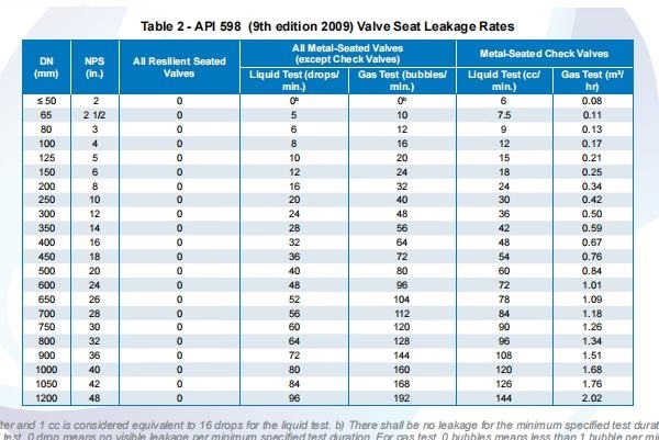
Table 5—Maximum Allowable Leakage Rates for Closure Tests c
| Valve Size | All Resilient- seated Valves | Metal Seated Valves Except Check | Metal Seated Check Valves | ||||
| DN (mm) | NPS (in.) | Liquid Test a (drops/min) | Gas Test a (bubbles/min) | Liquid Test (cc/min) | Gas Test (m3/h) | Gas Test (ft3/h) | |
| < 50 | < 2 | 0 | 0 b | 0 b | 6 | 0.08 | 3 |
| 65 | 2-1/2 | 0 | 5 | 10 | 7.5 | 0.11 | 3.75 |
| 80 | 3 | 0 | 6 | 12 | 9 | 0.13 | 4.5 |
| 100 | 4 | 0 | 8 | 16 | 12 | 0.17 | 6 |
| 125 | 5 | 0 | 10 | 20 | 15 | 0.21 | 7.5 |
| 150 | 6 | 0 | 12 | 24 | 18 | 0.25 | 9 |
| 200 | 8 | 0 | 16 | 32 | 24 | 0.34 | 12 |
| 250 | 10 | 0 | 20 | 40 | 30 | 0.42 | 15 |
| 300 | 12 | 0 | 24 | 48 | 36 | 0.50 | 18 |
| 350 | 14 | 0 | 28 | 56 | 42 | 0.59 | 21 |
| 400 | 16 | 0 | 32 | 64 | 48 | 0.67 | 24 |
| 450 | 18 | 0 | 36 | 72 | 54 | 0.76 | 27 |
| 500 | 20 | 0 | 40 | 80 | 60 | 0.84 | 30 |
| 600 | 24 | 0 | 48 | 96 | 72 | 1.01 | 36 |
| 650 | 26 | 0 | 52 | 104 | 78 | 1.09 | 39 |
| 700 | 28 | 0 | 56 | 112 | 84 | 1.18 | 42 |
| 750 | 30 | 0 | 60 | 120 | 90 | 1.26 | 45 |
| 800 | 32 | 0 | 64 | 128 | 96 | 1.34 | 48 |
| 900 | 36 | 0 | 72 | 144 | 108 | 1.51 | 54 |
| 1000 | 40 | 0 | 80 | 160 | 120 | 1.68 | 60 |
| 1050 | 42 | 0 | 84 | 168 | 126 | 1.76 | 63 |
| 1200 | 48 | 0 | 96 | 192 | 144 | 2.02 | 72 |
a For the liquid test, 1 mL is considered equivalent to 16 drops. For the gas test 1 mL is considered equivalent to 100 bubbles.
b There shall be no leakage for the minimum specified test duration (see Table 4). For liquid test, 0 drops means no visible leakage per minimum specified test duration. For standard gas test, 0 bubbles means less than 1 bubble per minimum specified test duration. For high-pressure pneumatic closure test refer to paragraph 5.4.
c Leakage rates for sizes above DN 1200 (NPS 48) shall be calculated by the following formulas:
Liquid Test for Metal Seated Valves except Check: 2 x NPS (drops/min)
Gas Test for Metal Seated Valves except Check: 4 x NPS (bubbles/min)
Liquid Test for Metal Seated Check Valves: 3 x NPS (cc/min)
Gas Test for Metal Seated Check Valves: 0.042 x NPS (m3/h)
Gas Test for Metal Seated Check Valves: 1.5 x NPS (ft3/h)
5 Pressure Tests
5.3 Tests Required
5.3.1 The pressure tests listed in Table 1 shall be performed on each valve in accordance with written procedures that comply with this standard.
5.3.3 Leakage rates for reduced bore valves shall be based on the DN (NPS) of the valve.
5.4 High-pressure Closure Test
The high-pressure closure test is required for several valve types, as shown in Table 1. For the valve types for which, according to Table 1, the high-pressure closure test is optional, the valves are still required to be able to pass the test (as a test of the design of the valve closure structure). Results of tests confirming the capacity of the valve design to pass the high-pressure closure test shall be supplied when requested in the purchase order. See Table 3, footnotes b and c, for calculation of test pressure.
5.5 High-pressure Pneumatic Shell Test
When specified in the purchase order, a high-pressure pneumatic shell test shall be performed. This test shall be performed after the shell test, using appropriate safety precautions. The pneumatic shell test pressure shall be 110 % of the maximum allowable pressure at 38 ℃ (100 °F) or as specified in the purchase order. Visible leakage is not allowed.
5.6 Test Fluid
5.6.1 For shell, high-pressure backseat, and high-pressure closure tests, the test fluid shall be air, inert gas, kerosene, water, or a noncorrosive liquid with a viscosity not higher than that of water. Unless otherwise specified in the purchase order, the test fluid temperature shall be within the range 5 °C (41 °F) to 38 °C (100 °F).
5.6.2 For the low-pressure closure and low-pressure backseat tests, the test fluid shall be air or inert gas.
5.6.3 When air or gas is used for closure, shell, or backseat tests, the valve manufacturer shall be capable of demonstrating the adequacy of the method of leakage detection.
5.6.4 Water used for any test can contain water-soluble oil and/or corrosion inhibitor. When specified by the purchaser, a wetting agent shall be included in the water. For testing of austenitic stainless steel valves, water with chloride content not exceeding 50 ppm shall be used. The valve manufacturer shall be able to document the chloride content.
5.7 Test Pressures
5.7.1 The shell test pressure shall be as listed in Table 2.
5.7.2 Backseat and closure test pressures shall be as listed in Table 3.
5.8 Test Duration
For each type of test, the required test pressure shall be maintained for at least the minimum time specified in Table 4.
5.9 Test Leakage
5.9.1 Shell, Stem Seals, and Backseat
5.9.1.1 For shell tests, visually detectable leakage through the pressure boundary walls and any fixed body joint is not permitted.
5.9.1.2 For backseat tests, visually detectable leakage is not permitted.
5.9.1.3 For valves with adjustable stem seals, leakage through the stem seals during the shell test shall not be cause for rejection when tested at prescribed pressure and duration. However, the manufacturer shall demonstrate that the stem seals are capable of retaining pressure at least equal to the 38 ℃ (100 °F) valve rating without visible leakage.
5.9.1.4 For valves with nonadjustable stem seals (O-rings, fixed single rings, and the like), visually detectable leakage during the shell test is not permitted.
5.9.1.5 Where no visually detectable leakage is permitted, the following definitions apply:
a)If the test fluid is a liquid, there shall be no visible evidence of drops or wetting of the external surfaces of the test valve.
b)If the test fluid is air or inert gas, no leakage will be revealed by the established detection method.
5.9.2 Closure
5.9.2.1 For both the low-pressure closure test and the high-pressure closure test, visual evidence of leakage through the disc, behind the seat rings, or past the shaft seals (of valves that have this feature) is not permitted and structural damage is not permitted. (Plastic [permanent] deformation of resilient seats and seals is not considered structural damage.) The allowable rate for leakage of test fluid at the seat-sealing surface interface, for the duration of the tests, is listed in Table 5.
5.9.2.2 The allowable leakage rate for closure tests of valves with nonmetallic (e.g. ceramic) seat materials shall be equal to that specified in Table 5 for a metal-seated valve of equivalent size and type.
5.9.2.3 As an alternative, displacement measuring devices may be used, provided that the detectable leakage rate is equivalent to that given in Table 5, the valve manufacturer shall demonstrate and validate that the procedure yields results equivalent to the requirements of this standard, and the device has been accepted by agreement between the purchaser and the manufacturer.
5.9.2.4 When volumetric devices (bubblers) are used to measure leakage, the test duration shall not begin until flow through the test tubing is established and stabilized. The device shall be calibrated to yield results equivalent to the units per minute listed in Table 5.
5.9.2.5 Bubbles per minute as tabulated are a suggested alternative based on a suitable calibrated measuring device, in this case, tubing with an ID ranging from 2 to 4 mm (0.100 to 0.150 in.) submerged in water to a depth of from 3 to 6 mm (0.125 to 0.250 in.). The tube end shall be cut square and smooth with no chamfers or burrs, and the tube axis shall be perpendicular to the surface of the water (see Figure 1).
6 Pressure Test Procedures
6.1 General
6.1.1 Valves designed to permit emergency or supplemental introduction of an injectable sealant to the seat area shall be tested with the injection system empty and not in use, except for lubricated plug valves.
6.1.2 When a liquid is used as the test fluid, the valve shall be essentially free from trapped air during the test.
6.1.3 Required protective coatings, such as paint, which can mask surface defects, shall not be applied to any surface before inspection or pressure testing. (Phosphatizing and similar chemical conversion processes used to protect valve surfaces are acceptable even if applied before the tests, provided that they will not seal off porosity.)
6.1.4 When closure testing valves, the valve manufacturer’s test procedure shall ensure that excessive force is not used to close the valve. The applied force may be determined from the appropriate figures in MSS SP-91[12] and shall be made available to the purchaser or testing facility upon request. The use of a supplemental leveraging device to aid in achieving a passing leakage rate is acceptable provided that the applied force does not exceed the manufacturer’s documented value. Where the manufacturer does not document or otherwise make available the maximum permissible force for valve closure, the test procedure shall restrict the use of supplemental leveraging devices.
6.2 Backseat Test
6.2.1 The backseat test is required for all valves, except for bellows seal valves, that have the backseat feature and shall be performed by applying pressure inside the assembled valve with the valve ends closed, the valve fully open, and the packing gland loose or packing not installed. If the backseat test is performed after the shell test, the packing shall be installed and/or packing glands retightened after the backseat test.
6.2.2 For valves DN 100 (NPS 4) and smaller, the backseat test may be combined with the shell test when volumetric devices are used to monitor leakage from the shell and backseat. When tested by this method, the packing shall be loose. The manufacturer shall be responsible for demonstrating that the packing will not leak at the valve’s rated pressure at 38 ℃ (100 °F).
6.2.3 The successful completion of the backseat test shall not be construed as recommendation by the valve manufacturer that, while the valve is pressurized, the valve may be repacked or packing may be replaced.
6.3 Shell Test
Except as provided in 6.2.2, the shell test shall be made by applying the pressure inside the assembled valve with the valve ends closed, the valve partially open, and any packing gland tight enough to maintain the test pressure, thereby, except for bellows seal valves, testing the stuffing box.
6.4 Low-pressure Closure Test
6.4.1 The low-pressure closure test shall be performed with the seat sealing surface interface clean and free from oil, grease, and sealant. If necessary to prevent galling, the sealing surfaces may be coated with a film of oil that is not heavier than kerosene. This requirement does not apply to a valve that uses a lubricant as its primary seal (e.g. lubricated plug valves).
6.4.2 Any leakage at the seat sealing surface interface, behind the seat ring, or through the disc on the open side of the valve shall be detected when bubbles are observed coming from the closure (disc, seat, and seat ring), covered with water or leakage that is channeled to a volumetric device for measurement.
6.4.3 When closure testing gate, plug, and downstream seated ball valves such as floating ball valves, a method of testing seat leakage shall be used that fills and fully pressurizes the body cavity to the test pressure between the seats and the bonnet area, as applicable, with the test fluid. This will ensure that no seat leakage can escape detection because of gradual filling of these volumes during the test period.
For a valve (other than a DBB valve or globe valve) designed to close against pressure from either direction, the pressure shall be applied successively to each side of the closed valve with the other side at atmospheric pressure to check for leakage at the atmospheric side of the closure. For a globe valve, pressure shall be applied in one direction with the pressure applied under the disc. DBB valves shall be tested as described in 6.6.
For a valve designed to close against pressure from one direction only and so marked, the pressure shall be applied on the pressure side of the valve only. For a check valve, the pressure shall be applied on the downstream side.
A closure test is required only in one direction for butterfly valves furnished with encapsulation or resilient internal liners and designed for use with Class 125 or Class 150 flanges (API Standard 609[7], Category A valves). For other resilient-seated butterfly valves (API Standard 609[7], Category B valves), the closure test is required in both directions. For butterfly valves with a preferred flow direction, the closure test in the nonpreferred direction shall be based on the reduced differential pressure rating in that direction.
6.4.4 Trapping test air or gas in the body cavity between the seats of a one-piece (solid or flexible) wedge gate valve and subsequently covering the seats with water or coating them with soap or a similar solution does not constitute an acceptable low-pressure closure test.
6.4.5 If a tapped connection in the body cavity is made to permit testing procedures described under DBB valve in 6.6, the connection shall be in accordance with MSS SP-45 and shall be fitted before shipment with a solid pipe plug (in accordance with ASME B16.11) material composition of which is equivalent to that of the valve shell.
6.5 High-pressure Closure Test
The procedure for the high-pressure closure test shall be the same as the procedure for the low-pressure closure test except that, in the case of a liquid test, leakage shall be detected when drops, not bubbles as described in 6.4 are observed.
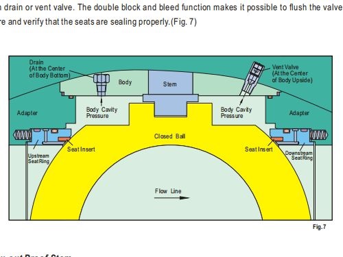
6.6 Double Block and Bleed High-pressure Closure Test
For a DBB valve, the pressure shall be applied successively to each side of the closure through the valve bore. Leakage into the body cavity shall be checked through an opening in the bottom of the valve (Position “G” per ASME B16.34). Where operational considerations do not allow for an opening in the bottom of the valve, an alternative opening location may be specified by the purchaser, and the valve shall be DBB tested in a position that results in the alternative opening location being at the bottom of the valve during test. Testing in all positions and specifically in alternative positions will require procedures that meet the requirement of 6.1.2. Test duration shall be no less than twice (2x) the values provided in Table 4.