Valve Cavity Relief Testing
Valve Cavity Relief Testing specifications in API 6D for trunnion ball valves, floating ball valves and Through-conduit Slab Gate Valves with Self-relieving Seats.
1.9.1 General
If the valve has one or more self-relieving seats or a relief system that connects the valve cavity to one side of the valve, the test shall conform to a documented procedure, by agreement.
Each valve shall be tested except valves that cannot trap pressure in the cavity.
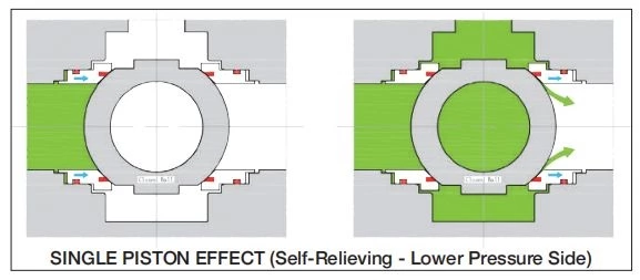
For valves where cavity overpressure relief is provided via one or more self-relieving seats, this shall be demonstrated by one of the cavity relief tests in I.9.2 or I.9.3.
For trunnion-mounted ball valves with self-relieving seats, selection of one of the three procedures of in I.9.2 shall be by agreement
1.9.2 Trunnion-mounted Ball Valves
1.9.2.1 Procedure 1—Internal Relieving Seats
The procedure for cavity-relief testing of trunnion-mounted ball valves with internal-relieving seats shall be as follows:
a) Fill the valve in the half-open position with hydrostatic test fluid and purge trapped air
b) Close the valve
c) Close the branch vents
d) Apply pressure to the valve cavity until one branch pressure starts to rise and the seat relieves the cavity pressure into the valve end; record this relief pressure and port location.
For valve types with two self-relieving seats, continue to increase the pressure to the cavity until the second branch pressure starts to rise and the second seat relieves; record the relief pressure of the second seat.
Failure to relieve at differential pressure less than 33 % of the valve pressure rating shall be cause for rejection.
EXAMPLE 1: Class 150, 275 psi (19.0 bar), the maximum rated pressure-relief pressure is 90 psi (6.2 bar).
EXAMPLE 2: Class 2500, 6250 psi (430.9 bar), the maximum rated pressure-relief pressure is 2060 psi (142.1 bar).
Failure to relieve pressure shall be cause for rejection.
Pressure-temperature ratings for class-rated valves shall conform to the applicable rating table for the appropriate material group in ASME B16.34 or MSS-SP 44.
1.9.2.2 Optional Procedure 2—One or More Self-relieving Seats
The procedure for cavity-relief testing of trunnion-mounted ball valves with one or more self-relieving seats shall be conducted using the following.
a) Fill the valve in the half-open position with hydrostatic test fluid.
b) Close the valve.
c) Pressurize both sides of the valve and the valve cavity simultaneously, up to 1.0 times rated working pressure (RWP).
d) Isolate both sides of the valve and the valve cavity from pressure source.
e) Slowly decrease pressure on one side while monitoring the valve cavity pressure. Record pressure on that side required to activate SPE seat seal relief (point at which valve cavity pressure decreases).
f) Repeat Steps a) to d) for the other side if it has a self-relieving seat.
Failure to relieve at a differential pressure less than 33% the valve pressure rating over the valve pressure rating shall be cause for rejection.
Pressure-temperature ratings for class-rated valves shall conform to the applicable rating table for the appropriate material group in ASME B16.34 or MSS-SP 44.
1.9.2.3 Procedure 3—Relief System Connecting Valve Cavity to One Valve Side
The procedure for cavity-relief testing of trunnion-mounted ball valves with a relief system that connects the valve cavity to one side of the valve shall be as follows:
a) Fill the valve in the half-open position with hydrostatic test fluid and purge trapped air
b) Close the valve
c) Close the branch vents
d) Apply pressure to the valve cavity until one branch pressure starts to rise; record this relief pressure and port location
Failure to relieve at differential pressure less than 33 % of the valve pressure rating shall be cause for rejection.
EXAMPLE 1: Class 150, 275 psi (19.0 bar), the maximum rated pressure-relief pressure is 90 psi (6.2 bar).
EXAMPLE 2: Class 2500, 6250 psi (430.9 bar), the maximum rated pressure-relief pressure is 2060 psi (142.1 bar).
1.9.3 Through-conduit Slab Gate Valves with Self-relieving Seats
Slab gate valves with one or more self-relieving seats that are upstream and/or downstream shall internally relieve the excess cavity pressure.
The procedure for cavity-relief testing of through-conduit slab gate valves with internal-relieving seats shall be as follows:
a) Fill the valve in the half-open position with hydrostatic test fluid and purge any trapped air
b) Close the valve (see NOTE 1)
NOTE 1
For through-conduit gate valves with rising stem hydrostatic test fluid volume may need to be adjusted during the closing stroke.
c) Close both branch vents
d) Apply design pressure (or other pressure agreed with the purchaser) via one of the valve branches with the opposite branch vented to atmosphere
e) Apply pressure to the valve cavity until the pressure in the pressurized branch starts to rise and the seat relieves the cavity pressure into the valve end; record this relief pressure
Failure to relieve at differential pressure less than 33% of the valve pressure rating over the valve pressure rating shall be cause for rejection
NOTE 2
For downstream sealing through-conduit gate valves, a center cavity pressure port is required.
1.9.4 Floating Ball Valves
19..4.1 Procedure 1
NOTE This procedure requires a test port in the valve body to have access to body cavity.
The test should be performed with a hydrostatic test fluid
The procedure shall be as follows:
a) Fill the valve in the half-open position with hydrostatic test fluid and purge trapped air
b) Close the valve
c) Apply pressure to the valve cavity until one branch pressure starts to release and the seat relieves the cavity pressure into the valve end; record this relief pressure and port location
Acceptance criteria shall be that the valve shall relieve at differential pressure less than 33 % of the valve pressure rating.
1.9.4.2 Procedure 2
NOTE This procedure does not require a test port in the valve body.
The test shall be performed with nitrogen
The procedure shall be as follows:
a) With the valve in half-open position, pressurize the valve to the valve pressure rating plus the maximum theoretical cavity relief pressure
b) Isolate the valve from the pressure source
c) Close the ball
d) Vent each end to atmospheric pressure
e) Isolate each end of the valve of the atmospheric pressure
f) Open the valve to the half-open position for the release of trapped pressure in the body cavity
g) Monitor the release pressure into the valve bore (only one pressure gauge can be used and installed)
Acceptance criteria shall be as follows:
—— Acceptance criteria of the release pressure shall be defined and calculated considering variation of initial pressure at volume of the valve body cavity (closed position) and final pressure at volume (volume of whole valve body + volume of the isolated test rig portion).
—— Monitored release pressure above the calculated criteria shall be cause for rejection.