API 6D Valve Testing Procedure, Pressure, Duration
Valve Pressure Test in API 6D includes the test procedure, test pressure, duration and acceptance criteria for the hydrostatic shell test, seat test and stem backseat test.
10.1 Pressure Testing—General
10.11 Procedure
Written test procedures that identify test methodology, test durations and acceptance criteria shall be developed and maintained for all pressure testing performed in conformance to this specification.
Each valve shall be tested in the fully assembled condition to the manufacture’s procedures prior to shipment.
Pressure testing shall be carried out before external coating of the valve.
NOTE- If the valve has been previously pressure tested to the requirements of this specification, subsequent repeat hydrostatic and gas testing may be performed without removal of the valve external coating.
Testing shall be performed in the sequence as listed in order of 10.3 to 10.4.5. The backseat test that is only applicable to valves per 10.2 shall be performed either immediately before or immediately after the hydrostatic shell test in 10.3.
10.1.2 Duration and Acceptance Criteria
Shell test duration and acceptance criteria shall be based on the NPS of the valve ends.
Seat test duration and acceptance criteria shall be based on the bore diameter of the closure member. Seat test duration and acceptance criteria for noncircular opening valves shall be based on the NPS of the valve ends.
The hydrostatic test fluid shall be water and shall contain a corrosion inhibitor. The chloride content of test water in contact with austenitic and duplex stainless-steel wetted components of valves shall not exceed 30 pg/g (30 ppm by mass). The chloride content in the test water shall be tested at least every 12 months and records shall be maintained in conformance with the documentation requirements of Section 14.
NOTE The hydrostatic test fluid may have antifreeze (glycol) added at the discretion of the manufacturer.
10.1.3 Test Conditions
Valves shall be tested with the seating and sealing surfaces free from sealant except where the sealant is the primary means of sealing. A secondary seat and/or stem packing sealant system, if provided, shall not be used before or during testing.
All hydrostatic and gas shell tests specified shall be:
—— performed with the valve unseated and partially open, or
—— performed with the valve fully open, provided the body cavity is simultaneously filled and pressurized through a cavity connection.
The supply pressure shall be isolated from the valve during hydrostatic shell testing and shall be stabilized prior to the start of pressure testing duration. The stabilization criteria shall be documented in the manufacturer’s pressure testing procedure.
The pressure measuring device shall be installed in the test apparatus in such a manner that the device indicates the test pressure of the valve assembly. The minimum test pressures shall be maintained for the duration of the test and shall be held for the minimum test durations as specified in 10.2, 10.3 or 10.4.
10.1.4 Leakage
For hydrostatic or gas testing, visible leakage (see 3.1.58) shall be any release of test fluid observed during the pressure hold period. Test fluid released during the seat test pressure build-up or pressure bleed-down shall not be recognized as visible leakage. Visible leakage shall be observed directly, including through a window, or by video equipment.
If video equipment is used in place of direct observation, resolution and brightness shall be maintained to ensure the detection of possible leakage.
10.2 Stem Backseat Test
Testing of the backseat shall be performed on valves that have this feature and shall commence with the packing gland loose unless a test port is provided. Self-energized packing or seals shall be removed unless a test port is provided for this test.
The valves shall be filled with the ends closed off and the closure member in the partially open position until leakage of the test fluid around the stem is observed. The backseat shall then be closed and a minimum pressure of 1.1 times the pressure rating determined in conformance with 4.3 for material at 100 °F (38 °C) based on the valve end connector material. The test duration shall conform to Table 8 based on the valve end connector size.
Table 8—Minimum Duration of Stem Backseat Tests
| Valve End Connector Size | Test Duration a (minutes) | |
| NPS | DN | |
| < 4 | < 100 | 2 |
| > 6 | > 150 | 5 |
NOTE: a Test duration starts once the valve is stabilized per manufacturer's procedures.
Warning—Due to the possibility of ejection of the stem from the valve body under high pressure, appropriate safety precautions must be taken.
Monitoring for leakage shall be through a test access port or by monitoring leakage around the loosened packing.
There shall be no visible leakage permitted during the backseat stem test.
10.3 Hydrostatic Shell Test
10.3.1 Hydrostatic Shell Test Preparation, Method and Acceptance Criteria
Valve ends shall be blocked and the closure member placed in the partially open position during the test.
When present, relief valves that release to the atmosphere shall be removed and their connection points plugged. Internal non-return valve shall be installed on sealant injection ports without the injection fitting.
The test pressure for the hydrostatic shell test shall be a minimum of 1.5 times the pressure rating conforming to 4.3 for material at 100 °F (38 °C) based on the valve end connector material. The test duration shall conform to Table 9 based on the valve end connector size.
Table 9—Minimum Duration of Hydrostatic Shell Tests
| Valve Size | Test Duration a (minutes) | |
| NPS | DN | |
| < 4 | < 100 | 2 |
| 6 to 10 | 150 to 250 | 5 |
| 12 to 18 | 300 to 450 | 15 |
| 20 and larger | 500 and larger | 30 |
NOTE: a Test duration starts once the valve is stabilized per manufacturer's procedures.
10.3.2 Extended Hydrostatic Shell Test
When the valve has been designed to withstand a higher hydrostatic shell test pressure per 5.5, the shell test pressure shall not be at less than 1.5 times the higher design pressure at 100 °F (38 °C).
When performing a higher hydrostatic shell test and the valve is flanged, the hydrostatic shell test shall be performed with bore sealing plugs that ensure the flanges are not subjected to test pressures greater than 1.5 times the valve flange rating.
The test duration specified in Table 9 shall start after stabilization.
There shall be no visible leakage permitted during the hydrostatic shell test.
NOTE: See Annex J for additional guidance on extended shell test.
10.3.3 Hydrostatic Shell Test with External Relief Valves
After hydrostatic shell testing, external relief valves shall be fitted to valves that have this feature. The connection to the valve body shall be tested at 95 % of the set pressure of the relief valve for 2 minutes for valve sizes up to and including NPS 4 (DN 100) and 5 minutes for valve sizes NPS 6 (DN 150) and larger. The relief-valve connection shall be free of visible leakage during this period.
The external relief valves shall be set to relieve at the specified pressure in accordance with 5.5.
10.3.4 Hydrostatic Shell Test with Pipe Pups
Hydrostatic shell test shall be required if pipe pups are to be welded to the valve as part of the final valve assembly by the manufacturer. Test pressure, duration, and acceptance criteria shall conform to 10.3.1
When the allowable test pressure rating of the pipe pup is less than the required hydrostatic test pressure, the valve shall first be hydrostatic tested without the pipe pups welded to the valve. Subsequently, the pipe pups shall be welded to the valve followed by a hydrostatic shell test of the assembly at a lower pressure than the design pressure specified by the purchaser.
The test duration specified in Table 9 shall start after stabilization.
There shall be no visible leakage permitted during the hydrostatic shell test with pipe pups.
10.3.5 Hydrostatic Test of Drain, Vent, and Sealant Injection Lines
If provided as part of the final assembly, drain, vent, and sealant injection lines shall be subject to a hydrostatic test with the valve.
If testing with the fully assembled valve is not practical, these lines shall be tested separately at the test pressure in 10.3.1. All fittings that are welded to the valve assembly shall be subjected to a hydrostatic pressure test in conformance with 10.3.1.
10.4 Seat Test
10.4.1 Hydrostatic Seat Test Preparation, Method and Acceptance Criteria
Lubricants or sealants shall be removed from seats and closure member sealing surfaces except where the lubricant or sealant is the primary means of sealing.
NOTE See K.14 for guidance on performing alternative hydrostatic seat testing.
The test pressure for all seat tests shall be a minimum of 1.1 times the pressure rating conforming to 4.3 for material at 100 °F (38 °C) based on the valve end connector material. The test duration shall conform to Table 10 based on the valve end connector size.
Table 10—Minimum Duration of Hydrostatic Seat Tests
| Valve End Connector Size | Test Duration a (minutes) | |
| NPS | DN | |
| < 4 | < 100 | 2 |
| 6 to 18 | 150 to 450 | 5 |
| 20 and larger | 500 and larger | 10 |
NOTE: a Test duration starts once the valve is stabilized per manufacturer’s procedures.
Seat leakage shall be monitored from the downstream side of the seat when under hydrostatic seat test.
The acceptance criteria for leakage shall be as follows:
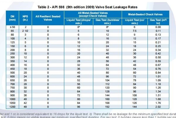
― For soft-seated valves and lubricated plug valves: leakage shall not exceed ISO 5208 Rate A (no visible leakage for the duration of the test at test pressure).
一 For metal-seated valves, other than check valves: leakage shall not exceed ISO 5208, Rate CD.
NOTE: The test procedures for various types of block valve are specified in 10.4.3.
― For metal-seated check valves: leakage shall not exceed ISO 5208, Rate E.
On completion of hydrostatic seat testing, parts such as drain plugs and cavity-relief valves, shall be fitted-in conformance with the manufacturer’s documented procedures.
10.4.2 Hydrostatic Seat Test—Check Valves
The hydrostatic seat test pressure for check valves shall be applied from the downstream direction of the required flow blockage.
10.4.3 Hydrostatic Seat Test—Block Valves
10.4.3.1 Unidirectional
With the valve half-open, the valve and its cavity shall be entirely filled with test fluid. The valve shall then be closed, and the test pressure applied to the appropriate end of the valve.
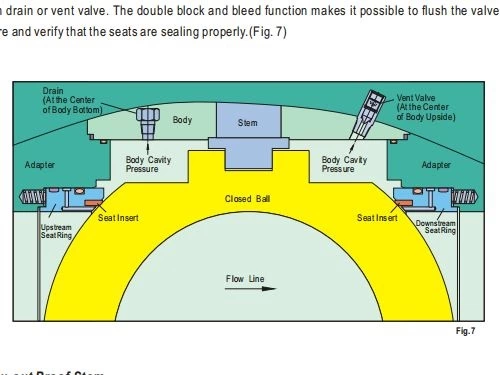
Leakage from the upstream seat shall be monitored via the valve body cavity vent or drain connection, where provided. For valves without a body cavity vent or drain connection or for downstream-seated valves, seat leakage shall be monitored at the respective downstream end of the valve (i.e., the valve end downstream of the pressurized test fluid).
10.4.3.2 Bidirectional
With the valve half-open, the valve and its cavity shall be entirely filled with test fluid. The valve shall then be closed, and the test pressure applied successively to both ends of the valve.
Seat leakage shall be monitored from each seat via the valve body cavity vent or drain connection, where provided. For valves without a body cavity vent or drain connection or for downstream-seated valves, seat leakage shall be monitored from the respective downstream end of the valve.
10.4.4 Certification of Cavity Relief Valve
If provided, the cavity relief valve (to the atmosphere) shall have the pressure set, tested, and certified to relieve to atmospheric pressure at the specified pressure by the relief-valve supplier or by the valve manufacturer.
The set pressure of relief valves shall be between 1.1 and 1.33 times the valve pressure rating conforming to 4.3 for material at 250 °F (121 °C). The reseat pressure shall not be less than 1.05 times the valve pressure rating conforming to 4.3 for material at 250 °F (121 °C). The manufacturer shall specify the set pressure of relief valves for temperatures above 250 °F (121 °C).